
Electric valve modification
The following are the core steps and technical points for retrofitting electric valves, combined with practical application scenarios:
1、 Core steps of modification
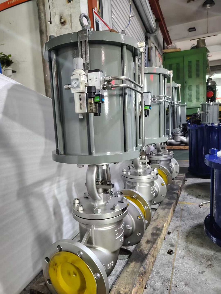
Matching and installation of actuators
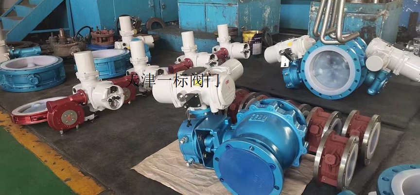
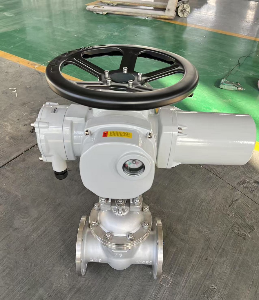
Remove the original manual valve handle and select an electric actuator based on the valve stem size (such as square hole), and achieve mechanical linkage through a variable diameter sleeve.
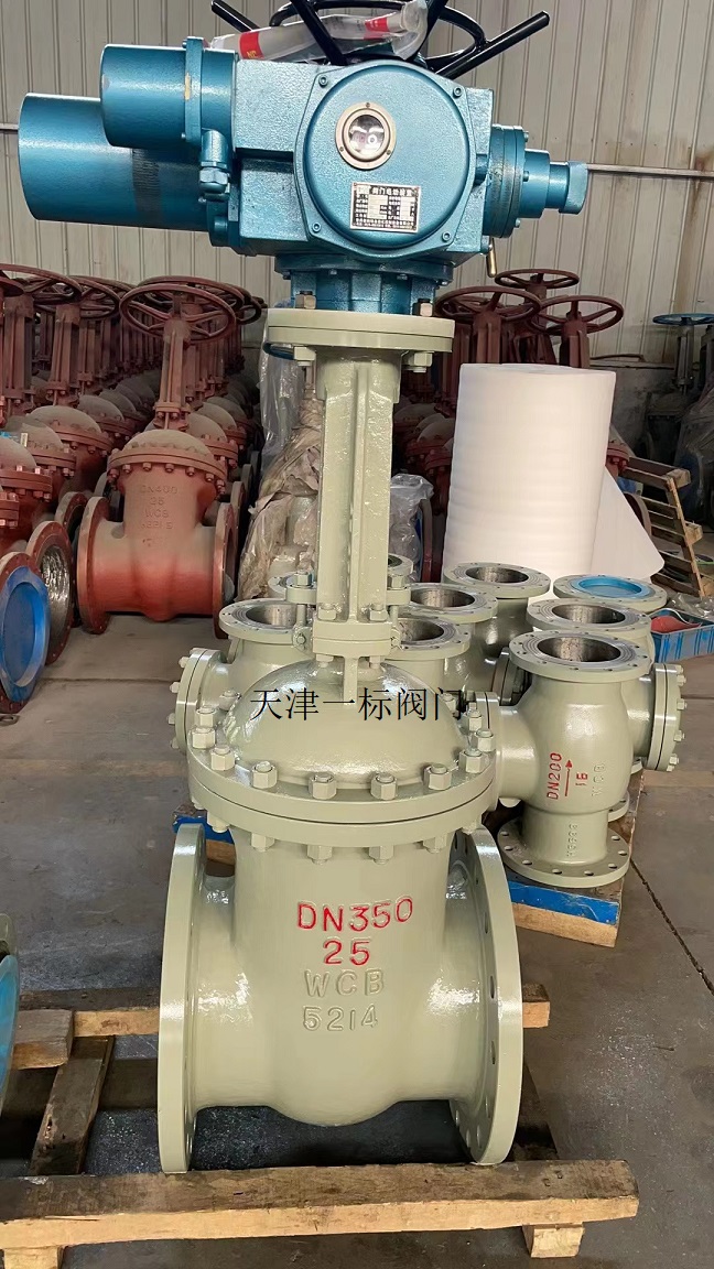
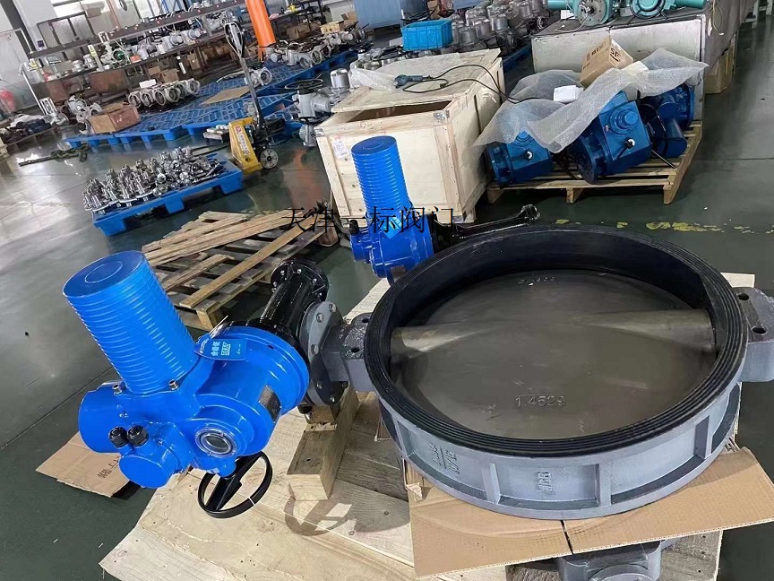
Large industrial valves (such as DN250 butterfly valves) require dedicated actuators, and their opening and closing synchronicity and torque adaptability should be tested after installation.
Control logic adjustment
Power off protection mode: Remove the valve body and connecting block screws, manually rotate the valve core to the target state (open/close), and after reassembly, achieve automatic power off opening and closing switching.
Dual control mode: In scenarios such as RV sewage valves, manual push rods can be retained as backups, and electric push rods can be installed through independent brackets to quickly switch to manual control in case of malfunctions.
Electrical system wiring
Power connection: Connect the live wire (L) to the brown terminal, the neutral wire (N) to the blue terminal, and the grounding wire resistance is ≤ 4 Ω.
Signal control:
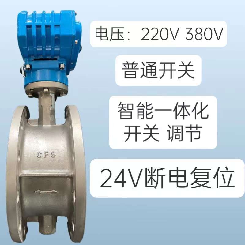
Switch type valve: The common terminal is connected to the control equipment common line, and the on/off valve line is tapped to the corresponding terminal.
Adjustable valve: The positive and negative poles of the 4-20mA signal line correspond to the input terminals of the actuator, and the feedback signal is connected to the controller to form a closed loop.
2、 Intelligent upgrade plan
Automated integration
Install a water immersion sensor linked to an electric valve, which automatically shuts off and closes the valve in case of water leakage, and remotely controls the opening and closing through a mobile app.
Industrial scenarios are connected to PLC systems to achieve precise pressure regulation and timed start stop.
Explosion proof system debugging
After unlocking the actuator, enter manual calibration mode and gradually calibrate the valve's fully closed (0 position) and fully open (full position) strokes to ensure that the signal is synchronized with the mechanical position.
3、 Key precautions
Sealing verification: After modification, a 1.1-fold pressure test is required to check the flange bolt torque and the sealing of the packing layer.
Safe operation:
Power off operation to avoid the risk of adsorption caused by dismantling the electromagnetic valve coil with electricity.
Three phase valves are strictly calibrated for phase sequence, while single-phase valves distinguish polarity.
Functional testing: Manually verify the flexibility of opening and closing, confirm the consistency between the opening indication and the action, and eliminate any jamming phenomenon.
Tip: For complex scenarios such as explosion-proof environments and large-diameter valves, it is recommended to refer to the wiring diagram in the original actuator manual and prioritize the use of corrosion-resistant stainless steel valve bodies.