
Explosion proof and flame retardant valve
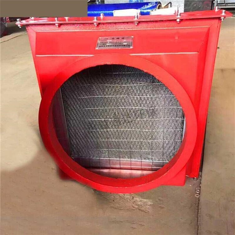
隔爆阻火阀 Fire and explosion prevention device
The new type of combustible gas pipeline flame arrester is a new product that has been updated and upgraded. The structure of the pipeline flame arrester is reasonable, and the flame retardant layer is made of stainless steel material, which is corrosion-resistant and easy to clean. The shell is made of various materials such as stainless steel, carbon steel, and cast steel, which can meet the needs of different process pipelines.
Pipeline flame arresters are mainly used on pipelines transporting flammable gases, torch systems, oil and gas recovery systems, fuel gas pipelines for heating furnaces, gas purification and purification systems, gas analysis systems, coal mine gas emission systems. The flame arresters have been tested for 13 consecutive subsonic flames and have been able to prevent the passage of flames each time.
Maintenance and upkeep of pipeline flame arresters: In order to ensure the safe use of flame arresters, they should be regularly inspected and maintained.
1. The flame arrester should be inspected every six months to check whether the flame arrester core is blocked, deformed, corroded, etc.
2. The blocked fire-resistant layer core should be cleaned thoroughly to ensure that each hole on the core is unobstructed, and any deformed or corroded fire-resistant layer should be replaced.
3. When reinstalling the fire-resistant layer core, it should be ensured that the joint surface is tight and there is no air leakage.
Explosion blocking mechanism
By quickly closing the mechanical valve disc, flame and pressure propagation are blocked when the explosion shock wave arrives, preventing chain reactions.
No external power is required, relying on explosive pressure to trigger actions (passive safety design).
Medium adaptability
Capable of handling dust (ST1-ST3 level) and gas explosion environments, suitable for detonation index Kst value ≤ 400 bar ・ m/s.
Allow normal airflow to pass through and automatically shut off only in the event of an explosion.
2、 Key parameters and selection
Application examples of parameter specification requirements
Diameter range DN25-DN1000 (1 "-40") for chemical pipelines and dust removal systems
Pressure rating PN10-PN63/ANSI 150-600. Customization is required for high-pressure working conditions
Installation distance from protective equipment ≤ 6m (DN ≤ 400 is 2m)
Cyclone separator outlet
Applicable standards ATEX 2014/34/EU, NFPA 68/69, GB/T 15605, multinational projects require multiple standard certifications
3、 Key points for installation and maintenance
Installation specifications
Directionality: The arrow on the valve body should be consistent with the flow direction of the medium. Reverse installation may cause failure.
Straight pipe section: A straight pipe section with a diameter of ≥ 5D (front) and 3D (back) should be retained before and after (D is the diameter of the pipe).
Maintenance requirements
Regularly check the flexibility of the valve disc and clean any accumulated dust or scale.
When connecting flanges, high-temperature resistant gaskets (such as graphite) should be used and bolts should be symmetrically tightened.
4、 Typical application scenarios
Chemical industry: Reactor inlet and outlet pipelines to prevent explosions from spreading to upstream equipment.
Grain processing: Dust collection system to block the spread of starch/sugar powder explosions.